- Published on
Creating a VLAN on OPNSense
- Authors
In this post, we will create a VLAN on opnsense, will add and configure it on a Netgear switch, and then add it to a Unifi Access Point to create a new WiFi network.
Note: this post is meant as a reference guide and does not go into detail about what a VLAN etc is. Those details can be found by reading the articles in the References section of this post.
Adding a VLAN on OPNSense
Create a new Interface
- Go to
Interfaces > Other Types > VLAN - Click
Add - Set each option in the new dialogue
Device--> Leave empty to generate the device nameParent--> This is the physical port where the VLAN should reside.VLAN tag--> The tag number of the VLAN. Should be something other than1, and should be different from existing VLANs you have created.VLAN priority--> The priority of the VLAN trafficDescription--> A short description of the VLAN
- Click
Applyto create and apply the new interface
Create logical interface
- After creating the new interface, from the previous section, your VLAN should now have a name under the
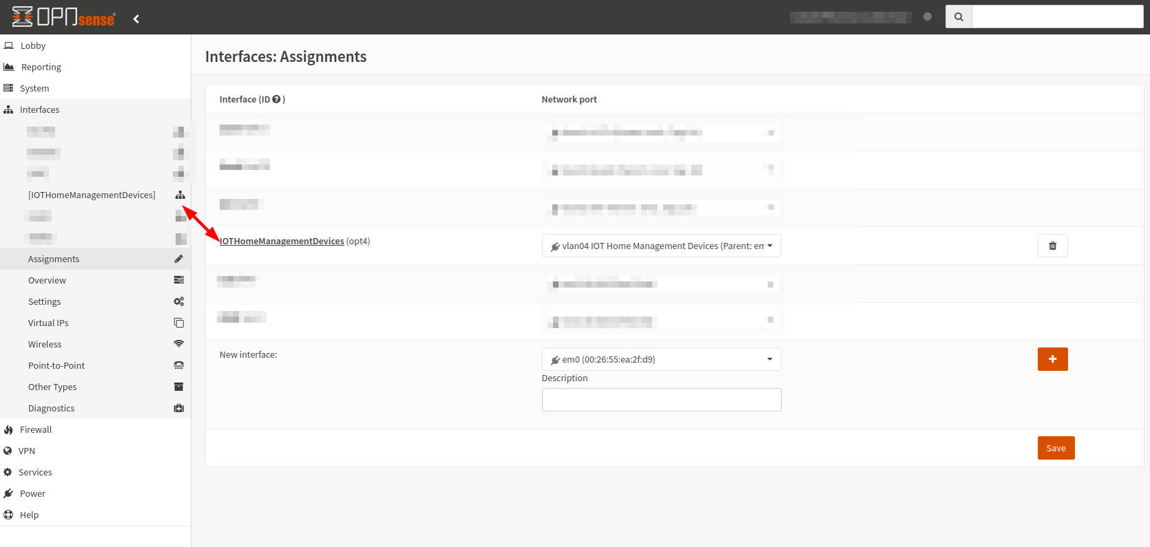
Devicecolumn. Make a note of it. - Go to
Interfaces > Assignments - In the selection box besides
New interface, select the new interface name from the previous step. - Click the
+button - Click
Saveto save the changes - The interface should now show up under the
Interfacesmenu, under the same name as theInterface (ID)in theAssignments page
- Select the new interface from the menu
- Check
Enable InterfaceandPrevent interface removal - In the
IPv4 Configuration Typeselection box, chooseStack IPv4(Note: Any other configuration is not covered by this post) - In the
IPv4 addressbox, choose an IP address you wish to use for the interface. For example, I have assigned an address of192.168.50.1, for my VLAN with a tag of50. I always assign.1as the gateway IP address for the VLAN.
Enable DHCP
- Go to
Services > DHCPv4 > [Name of new interface] - Click
Enable DHCP server on the [Name of new interface] interface - Enter a range of IP addresses that you wish the clients in the VLAN to use.
Note: If you get a No available address range for configured interface subnet size warning in the Available range box, your IPv4 address settings from the previous step are too restrictive. For example, you may have set a CIDR suffix to /32 which only allows for one host.
- Click
Save
Add Firewall Rules
In this section we will assume WAN traffic should be allowed, but everything else (e.g. traffic within the VLAN, or to other VLANs) should be blocked.
- Go to
Firewall > Aliases - Create a new alias
Enabled--> checkedName-->Internal_NetworksType-->Network(s)Categories--> leave blankContent--> Add all IP addresses for your internal network. For example I have192.168.1.1/24,192.168.20.1/24,192.168.30.1/24,192.168.40.1/24, and192.168.50.1/24.Description-->All internal IP addresses
- Click
Apply - Go to
Firewall > Rules > [Name of new interface] - Create a new rule
Action-->BlockDisabled--> uncheckedQuick--> checkedApply the action immediately on matchInterface-->[Name of new interface]Direction-->inTCP/IP Version-->IPv4Protocol-->anySource / Invert--> uncheckedSource-->[Name of new interface] netDestination / Invert--> uncheckedDestination-->Internal_NetworksDestination port range-->from: any,to: anyLog--> checkedLog packets that are handled by this ruleCategory--> leave blankDescription-->Blocks all internal IP addressesAdvanced features--> leave as defaults
- Click
Save - Create a new rule
Action-->PassDisabled--> uncheckedQuick--> checkedApply the action immediately on matchInterface-->[Name of new interface]Direction-->inTCP/IP Version-->IPv4Protocol-->anySource / Invert--> uncheckedSource-->[Name of new interface] netDestination / Invert--> uncheckedDestination-->anyDestination port range-->from: any,to: anyLog--> uncheckedCategory--> leave blankDescription-->Default allow LAN to any ruleAdvanced features--> leave as defaults
- Make sure the Block rule is above the Allow rule, as OPNSense will apply the rules from top to bottom.
- Click
Save - Click
Apply changes
Adding a VLAN to a Netgear switch
Note: These steps will only work on a managed switch.
If you're model of switch is not listed below, your steps may differ.
GS308E
These steps are relevant to the Netgear switch model GS308E.
- Navigate to the IP address of the switch in a browser
- Go to
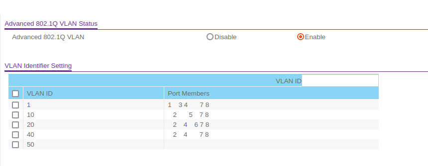
VLAN > 802.1Q > Advanced > VLAN Configuration - Set
Advanced 802.1Q VLANtoEnable. - When prompted, click
OK. - In the
VLAN IDfield, enter the ID of the VLAN you wish to create and clickAdd. Note: This is the ID from the very first step of this post, where we assigned a VLAN tag.
In this example, I added a VLAN ID of 50.
- Go to
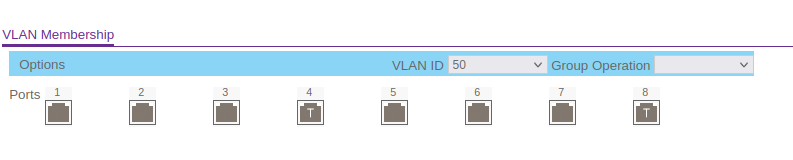
Go to VLAN > 802.1Q > Advanced > VLAN Membership - In the
VLAN IDdrop down menu, select the VLAN ID you just added - Click each port until you get the required configuration (
Tfor trunk port,Ufor access port) - Click
Apply.
In this example I've set port 8 to T, so it can pass traffic through to my second managed switch, and port 4 to T, so I can set-up a new Wifi Network with my Unifi APs.
GS724T
These steps are relevant to the Netgear switch model GS724T.
- Navigate to the IP address of the switch in a browser
- Go to
Switching > VLAN > Advanced > VLAN Configuration - Add the
VLAN ID,VLAN Name, and setVLAN Typetostatic - Click
Add - Go to
Switching > VLAN > Advanced > VLAN Membership - In the
VLAN IDdrop down menu, select the VLAN ID you just added - Click each port until you get the required configuration (
Tfor trunk port,Ufor access port) - Click
Apply.
Changing a Access port between VLAN IDs
In this example, port 19 is currently assigned to VLAN 1 (LAN), but I am moving it to VLAN 50.
- Go to
Switching > VLAN > Advanced > VLAN Membership - In the
VLAN IDdrop down menu, select VLAN ID50 - Click port
19until it showsU - Click
Apply - Go to
Switching > VLAN > Advanced > Port PVID Configuration - Select port
19(g19) - Change the
Configured PVIDfield from1to50and theVLAN Memberfield from1,50to50 - Click
Apply - Go to
Switching > VLAN > Advanced > VLAN Membership - In the
VLAN IDdrop down menu, select VLAN ID1 - Click port
19until it is blank - Click
Apply
Adding a new WiFi Network to Unifi AP
Create Network
- Navigate to Unifi Network in your browser
- Go to
Settings > Networks - Click
Create New NetworkNetwork Name- The name of the new networkAuto Scale Network- UncheckedHost Address- The gateway IP assigned in OPNsense (e.g.192.168.50.1)Advanced Configuration-ManualVLAN ID- The ID of the VLAN that was createdNetwork Type-StandardIGMP Snooping- UncheckedMulticast DNS- UncheckedDHCP- Leave default settings
- Click
Add Network
Create new WiFi Network
- Go to
Settings > WiFi - Click
Create New WiFi NetworkName- SSID of the new WiFi NetworkPassword- Password of the new WiFi NetworkNetwork- Name of the network from the previous stepBroadcasting APs- APs you want to broadcast the new SSID
- Click
Add WiFi Network